2.2 Images: "image.ss"
The image teachpack provides a number of basic image construction functions, along with
combinators for building more complex images out of existing images. Basic images include
various polygons, ellipses and circles, and text, as well as bitmaps (typically bitmaps
come about via the Insert Image... menu item in DrRacket).
Existing images can be rotated, scaled, flipped, and overlaid on top of each other.
2.2.1 Basic Images
Constructs a circle with the given radius, height, mode, and color.
If the mode is 'outline or "outline", then the last
argument can be a pen struct or an image-color?, but if the mode
is 'solid or "solid", then the last argument must be an
image-color?.
Constructs an ellipse with the given width, height, mode, and color.
If the mode is 'outline or "outline", then the last
argument can be a pen struct or an image-color?, but if the mode
is 'solid or "solid", then the last argument must be an
image-color?.
Constructs an image representing a line segment that connects the points
(0,0) to (x1,y1).
Examples: |
| > (line 30 30 "black") | 
| | > (line -30 20 "red") | 
| | > (line 30 -20 "red") | 
|
|
Adds a line to the image
image, starting from the point (
x1,
y1)
and going to the point (
x2,
y2).
Unlike
scene+line, if the line passes outside of
image, the image
gets larger to accommodate the line.
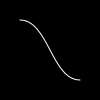
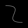
Adds a curve to image, starting at the point
(x1,y1), and ending at the point
(x2,y2).
The angle1 and angle2 arguments specify the
angle that the curve has as it leaves the initial point and
as it reaches the final point, respectively.
The pull1 and pull2 arguments control how
long the curve tries to stay with that angle. Larger numbers
mean that the curve stays with the angle longer.
Unlike scene+curve, if the line passes outside of image, the image
gets larger to accommodate the curve.
Constructs an image that draws the given string, using the font size and color.
Examples: |
| > (text "Hello" 24 "olive") | 
| | > (text "Goodbye" 36 "indigo") | 
|
|
Constructs an image that draws the given string, using a complete font specification.
The face and the family combine to give the complete typeface. If
face is available on the system, it is used, but if not then a default typeface
based on the family is chosen. The style controls if the face is italic
or not (on Windows and Mac OS X, 'slant and 'italic are the same),
the weight controls if it is boldface (or light), and underline?
determines if the face is underlined. For more details on these arguments, see font%,
which ultimately is what this code uses to draw the font.
Examples: |
| > (text/font "Hello" 24 "olive" | | "Gill Sans" 'swiss 'normal 'bold #f) |
| 
| | > (text/font "Goodbye" 18 "indigo" | | #f 'modern 'italic 'normal #f) |
| 
| | > (text/font "not really a link" 18 "blue" | | #f 'roman 'normal 'normal #t) |
| 
|
|
The empty image. Its width and height are both zero and it does not draw at all.
2.2.2 Polygons
Constructs a upward-pointing equilateral triangle.
The side-length argument
determines the
length of the side of the triangle.
If the mode is 'outline or "outline", then the last
argument can be a pen struct or an image-color?, but if the mode
is 'solid or "solid", then the last argument must be an
image-color?.
Constructs a triangle with a right angle where the two sides adjacent
to the right angle have lengths side-length1 and side-length2.
If the mode is 'outline or "outline", then the last
argument can be a pen struct or an image-color?, but if the mode
is 'solid or "solid", then the last argument must be an
image-color?.
Creates a triangle with two equal-length sides, of length side-length
where the angle between those sides is angle. The third
leg is straight, horizontally. If the angle is less than
180, then the triangle will point up and if the angle
is more, then the triangle will point down.
If the mode is 'outline or "outline", then the last
argument can be a pen struct or an image-color?, but if the mode
is 'solid or "solid", then the last argument must be an
image-color?.
To create a triangle given known sides and angles, the following
family of functions are useful:
They all construct a triangle oriented as follows:
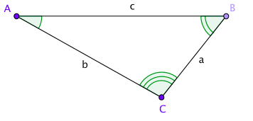
Creates a triangle where the side lengths a, b, and, c are given by side-length-a,
side-length-b, and, side-length-c respectively.
If the mode is 'outline or "outline", then the last
argument can be a pen struct or an image-color?, but if the mode
is 'solid or "solid", then the last argument must be an
image-color?.
Creates a triangle where the angle A and side length a and b, are given by angle-a,
side-length-b, and, side-length-c respectively.
See above for a diagram showing where which sides and which angles are which.
If the mode is 'outline or "outline", then the last
argument can be a pen struct or an image-color?, but if the mode
is 'solid or "solid", then the last argument must be an
image-color?.
Creates a triangle where the side length a, angle B, and, side length c given by side-length-a,
angle-b, and, side-length-c respectively.
See above for a diagram showing where which sides and which angles are which.
If the mode is 'outline or "outline", then the last
argument can be a pen struct or an image-color?, but if the mode
is 'solid or "solid", then the last argument must be an
image-color?.
Creates a triangle where the side length a, side length b, and, angle c given by side-length-a,
side-length-b, and, angle-c respectively.
See above for a diagram showing where which sides and which angles are which.
If the mode is 'outline or "outline", then the last
argument can be a pen struct or an image-color?, but if the mode
is 'solid or "solid", then the last argument must be an
image-color?.
Creates a triangle where the angle A, angle B, and, side length c given by angle-a,
angle-b, and, side-length-c respectively.
See above for a diagram showing where which sides and which angles are which.
If the mode is 'outline or "outline", then the last
argument can be a pen struct or an image-color?, but if the mode
is 'solid or "solid", then the last argument must be an
image-color?.
Creates a triangle where the angle A, side length b, and, angle C given by angle-a,
side-length-b, and, angle-c respectively.
See above for a diagram showing where which sides and which angles are which.
If the mode is 'outline or "outline", then the last
argument can be a pen struct or an image-color?, but if the mode
is 'solid or "solid", then the last argument must be an
image-color?.
Creates a triangle where the side length a, angle B, and, angle C given by side-length-a,
angle-b, and, angle-c respectively.
See above for a diagram showing where which sides and which angles are which.
If the mode is 'outline or "outline", then the last
argument can be a pen struct or an image-color?, but if the mode
is 'solid or "solid", then the last argument must be an
image-color?.
Constructs a square.
If the mode is 'outline or "outline", then the last
argument can be a pen struct or an image-color?, but if the mode
is 'solid or "solid", then the last argument must be an
image-color?.
Examples: |
| > (square 40 "solid" "slateblue") | 
| | > (square 50 "outline" "darkmagenta") | 
|
|
Constructs a rectangle with the given width, height, mode, and color.
If the mode is 'outline or "outline", then the last
argument can be a pen struct or an image-color?, but if the mode
is 'solid or "solid", then the last argument must be an
image-color?.
Constructs a four sided polygon with all equal sides and thus where opposite angles are equal to each
other. The top and bottom pair of angles is
angle and the left and right are
(- 180 angle).
If the mode is 'outline or "outline", then the last
argument can be a pen struct or an image-color?, but if the mode
is 'solid or "solid", then the last argument must be an
image-color?.
Examples: |
| > (rhombus 40 45 "solid" "magenta") | 
| | > (rhombus 80 150 "solid" "mediumpurple") | 
|
|
Constructs a star with five points. The side-length argument
determines the side length of the enclosing pentagon.
If the mode is 'outline or "outline", then the last
argument can be a pen struct or an image-color?, but if the mode
is 'solid or "solid", then the last argument must be an
image-color?.
Example: |
| > (star 40 "solid" "gray") | 
|
|
Constructs an arbitrary regular star polygon (a generalization of the regular polygons).
The polygon is enclosed by a regular polygon with side-count sides each
side-length long. The polygon is actually constructed by going from vertex to
vertex around the regular polgon, but skipping over every step-count vertices.
For examples, if side-count is 5 and step-count is 2,
then this function produces a shape just like star.
If the mode is 'outline or "outline", then the last
argument can be a pen struct or an image-color?, but if the mode
is 'solid or "solid", then the last argument must be an
image-color?.
Constructs a star-like polygon where the star is specified by two radii and a number of points.
The first radius determines where the points begin, the second determines where they end, and
the point-count argument determines how many points the star has.
Constructs a regular polygon with side-count sides.
If the mode is 'outline or "outline", then the last
argument can be a pen struct or an image-color?, but if the mode
is 'solid or "solid", then the last argument must be an
image-color?.
Constructs a polygon connecting the given vertices.
If the mode is 'outline or "outline", then the last
argument can be a pen struct or an image-color?, but if the mode
is 'solid or "solid", then the last argument must be an
image-color?.
2.2.3 Overlaying Images
Overlays all of its arguments building a single image. The first argument goes
on top of the second argument, which goes on top of the third argument, etc.
The images are all lined up on their centers.
Overlays all of its image arguments, much like the
overlay function, but using
x-place and
y-place to determine where the images are lined up. For example, if
x-place and
y-place are both
"middle", then the images are lined up
on their centers.
Just like
overlay, this function lines up its image arguments on top of
each other. Unlike
overlay, it moves
i2 by
x pixels to
the right and
y down before overlaying them.
Overlays image i1 on top of i2, using x-place and y-place as the
starting points for the overlaying, and then adjusts i2 by x to the right and
y pixels down.
This function combines the capabilities of overlay/align and overlay/offset.
Constructs an image by overlaying i1 on top of i2.
The images are initially lined up on their upper-left corners and
then i2 is shifted to the right
by x pixels to and down by y pixels.
This is the same as (underlay/xy i2 (- x) (- y) i1).
See also overlay/offset and underlay/offset.
Underlays all of its arguments building a single image.
It behaves like overlay, but with the arguments in the reverse order.
That is, the first argument goes
underneath of the second argument, which goes underneath the third argument, etc.
The images are all lined up on their centers.
Underlays all of its image arguments, much like the
underlay function, but using
x-place and
y-place to determine where the images are lined up. For example, if
x-place and
y-place are both
"middle", then the images are lined up
on their centers.
Just like
underlay, this function lines up its first image argument
underneath the second. Unlike
underlay, it moves
i2 by
x pixels to the right and
y down before underlaying them.
Underlays image i1 underneath i2, using x-place and y-place as the
starting points for the combination, and then adjusts i2 by x to the right and
y pixels down.
This function combines the capabilities of underlay/align and underlay/offset.
Constructs an image by underlaying i1 underneath i2.
The images are initially lined up on their upper-left corners and
then i2 is shifted to the right
by x pixels to and down by y pixels.
This is the same as (overlay/xy i2 (- x) (- y) i1).
See also underlay/offset and overlay/offset.
Constructs an image by placing all of the argument images in a
horizontal row, aligned along their centers.
Constructs an image by placing all of the argument images in a horizontal row, lined
up as indicated by the y-place argument. For example, if y-place
is "middle", then the images are placed side by side with their centers
lined up with each other.
Constructs an image by placing all of the argument images in a
vertical row, aligned along their centers.
Constructs an image by placing all of the argument images in a vertical row, lined
up as indicated by the x-place argument. For example, if x-place
is "middle", then the images are placed above each other with their centers
lined up.
2.2.4 Placing Images & Scenes
Placing images into scenes is particularly useful when building worlds
and universes using 2htdp/universe.
Creates an empty scene, i.e., a white rectangle with a black outline.
The three-argument version creates a rectangle of the specified color with
a black outline.
Places image onto scene with its center at the coordinates
(x,y) and crops the resulting image so that it has the
same size as scene. The coordinates are relative to the top-left
of scene.
Adds a line to the image
scene, starting from the point (
x1,
y1)
and going to the point (
x2,
y2); unlike
add-line, this function crops the resulting image to the size of
scene.
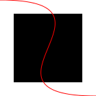
Adds a curve to scene, starting at the point
(x1,y1), and ending at the point
(x2,y2).
The angle1 and angle2 arguments specify the
angle that the curve has as it leaves the initial point and
as it reaches the final point, respectively.
The pull1 and pull2 arguments control how
long the curve tries to stay with that angle. Larger numbers
mean that the curve stays with the angle longer.
Unlike add-curve, this function crops the curve, only showing
the parts that fit onto scene.
2.2.5 Rotating, Scaling, Flipping, Cropping, and Framing Images
Rotates image by angle degrees in a counter-clockwise direction.
Scales image by factor.
The pen sizes are also scaled and thus draw thicker (or thinner)
lines than the original image, unless the pen was size
0. That pen size is treated specially to mean “the
smallest available line” and thus it always draws a one pixel
wide line; this is also the case for 'outline and "outline"
shapes that are drawn with an image-color? instead of
a pen.
Scales image by x-factor horizontally and by
y-factor vertically.
Flips image left to right.
Flipping images with text is not supported (so passing flip-horizontal an image
that contains a text or text/font image inside somewhere signals an error).
Flips image top to bottom.
Flipping images with text is not supported (so passing flip-vertical an image
that contains a text or text/font image inside somewhere signals an error).
Crops image to the rectangle with the upper left at the point (x,y)
and with width and height.
Examples: |
| > (crop 0 0 40 40 (circle 40 "solid" "chocolate")) | 
| | > (crop 40 60 40 60 (ellipse 80 120 "solid" "dodgerblue")) | 
| | 
|
|
Returns an image just like image, except
with a black, single pixel frame drawn around the
bounding box of the image.
Generally speaking, this function is useful to
debug image constructions, i.e., to see where
certain sub-images appear within some larger image.
2.2.6 Bitmaps
DrRacket’s Insert Image ...
menu item allows you to insert images into your program text, and those images are treated
as images for this library.
Unlike all of the other images in this library, those images (and the other images created
by functions in this section of the documentation)
are represented as bitmaps, i.e., an array of colors (that can be quite large in some cases).
This means that scaling and rotating them loses fidelity in the image and is significantly
more expensive than with the other shapes.
| (bitmap bitmap-spec) |
| |
| bitmap-spec | | = | | rel-string | | | | | | | id |
|
Loads the bitmap specified by bitmap-spec. If
bitmap-spec is a string, it is treated as a relative path.
If it is an identifier, it is treated like a require spec and used to
refer to a file in a collection.
Goes out on the web and downloads the image at url.
Downloading the image happens each time this function is called, so
you may find it simpler to download the image once with a browser
and then paste it into your program or download it and use bitmap.
Returns a list of colors that correspond to the colors in the
image, reading from left to right, top to bottom.
Examples: |
| > (image->color-list (rectangle 2 2 "solid" "black")) | (list (color 0 0 0 255) (color 0 0 0 255) (color 0 0 0 255) (color 0 0 0 255)) | | (list (color 1 1 1 255) (color 2 2 2 255) (color 3 3 3 255) (color 4 4 4 255)) |
|
Constructs a bitmap from the given colors, with the given width and height.
Freezing an image internally builds a bitmap, crops the image, draws the cropped image
into the bitmap and then
uses the bitmap to draw that image afterwards. Typically this is used as a performance
hint. When an image both contains many sub-images and is going to be drawn many times
(but not scaled or rotated),
using freeze on the image can substantially improve performance without changing how
the image draws.
If freeze is passed only the image argument, then it crops the image to its bounding
box. If it is given three arguments, the two numbers are used as the width and height and
the five argument version fully specifies where to crop the image.
2.2.7 Image Properties
Returns the width of i.
Returns the height of i.
Returns the distance from the top of the image to its baseline.
Unless the image was constructed with
text,
text/font
or, in some cases,
crop, this will be the same as its height.
A cropped image’s baseline is the same as the image’s baseline, if the
cropping stays within the original image’s bounding box. But if the cropping actually
enlarges the image, then the baseline can end up being smaller.
2.2.8 Image Predicates
This section lists predicates for the basic structures provided by the image library.
Additionally, images inserted into a DrRacket window are treated as
bitmap images, as are instances of image-snip% and bitmap%.
Determines if x is a mode suitable for
constructing images.
It can be one of
'solid, "solid", 'outline,
or "outline", indicating if the shape is
filled in or not.
It can also be an integer between 0 and 255 (inclusive)
indicating the transparency of the image. The integer 255 is
fully opaque, and is the same as "solid" (or 'solid).
The integer 0 means fully transparent.
Determines if
x represents a color. Strings, symbols,
and
color structs are allowed as colors.
For example,
"magenta", "black", 'orange, and 'purple
are allowed. Colors are not case-sensitive, so
"Magenta", "Black", 'Orange, and 'Purple
are also allowed, and are the same colors as in the previous sentence.
If a string or symbol color name is not recognized, black is used in its place.
The complete list of colors is available in the documentation for
color-database<%>.
|
| red : (and/c natural-number/c (<=/c 255)) |
| green : (and/c natural-number/c (<=/c 255)) |
| blue : (and/c natural-number/c (<=/c 255)) |
| alpha : (and/c natural-number/c (<=/c 255)) |
The
color struct defines a color with
red,
green,
blue, and
alpha components
that range from
0 to
255.
The red, green, and blue fields
combine to make a color, with the higher values meaning more of the given color.
For example, (make-color 255 0 0) makes a
bright red color and (make-color 255 0 255) makes a bright purple.
The alpha field controls the transparency of the color. A value of 255 means
that the color is opaque and 0 means the color is fully transparent.
The constructor, make-color, also accepts only three arguments, in which case
the three arguments are used for the red, green, and blue fields, and the
alpha field defaults to 255.
Determines if x is a placement option
for the vertical direction. It can be one
of
"top",
'top,
"bottom",
'bottom,
"middle",
'middle,
"center",
'center,
"baseline",
'baseline,
"pinhole", or
'pinhole.
The baseline of an image is the place where the bottoms any letters line up, not counting descenders, e.g. the tail on “y” or “g” or “j”.
Using "pinhole" or 'pinhole is only allowed when all of the image arguments have pinholes.
Determines if x is a placement option
for the horizontal direction. It can be one
of "left",
'left,
"right",
'right,
"middle",
'middle,
"center",
'center,
"pinhole", or
'pinhole.
Using "pinhole" or 'pinhole is only allowed when all of the image arguments have pinholes.
Determines if x is an angle, namely
a real number between 0 (inclusive)
and 360 (exclusive).
Determines if x is an integer
greater than or equal to 3.
Determines if x is an integer greater than or equal to 1.
Determines if
x is a
posn whose
x and
y
fields are both
real? numbers.
The
pen struct specifies how the drawing library draws lines.
A good default for style is "solid", and
good default values for the cap and join fields
are "round".
Using 0 as a width is special; it means to always draw the
smallest possible, but visible, pen. This means that the pen will always
be one pixel in size, no matter how the image is scaled.
Determines if x is a valid pen style.
It can be one of
"solid", 'solid,
"dot", 'dot,
"long-dash", 'long-dash,
"short-dash", 'short-dash,
"dot-dash", or 'dot-dash.
Determines if x is a valid pen cap.
It can be one of
"round", 'round,
"projecting", 'projecting,
"butt", or 'butt.
Determines if x is a valid pen join.
It can be one of
"round", 'round,
"bevel", 'bevel,
"miter", or 'miter.
2.2.9 Equality Testing of Images
Two images are equal? if they draw exactly the same way at their current size
(not necessarily at all sizes) and, if there are pinholes, the pinholes are
in the same place.
2.2.10 Pinholes
A pinhole is an optional property of an image that identifies a point somewhere
in the image. The pinhole can then be used to facilitate overlaying images by
lining them up on the their pinholes.
When an image has a pinhole, the pinhole
is drawn with crosshairs on the image.
The crosshairs are drawn with a two one pixel wide black lines (one horizontal and one vertical)
and two one pixel wide white lines,
where the black lines is drawn .5 pixels to the left and above the pinhole, and the
white lines are drawn .5 pixels to the right and below the pinhole.
Accordingly, when the pixel is on an integral coordinate, then black and white lines all
take up a single pixel and in the center of their intersections is the actual pinholes.
See The nitty gritty of pixels, pens, and lines for more details about pixels.
When images are overlay’d, underlay’d (or the variants of those functions),
placed beside, or above each other,
the pinhole of the resulting image is the pinhole of the first image argument passed to the combining
operation. When images are combined with place-image (or the variants of place-image),
then the scene argument’s pinhole is preserved.
Creates a pinhole in image at its center.
Creates a pinhole in image at the point (x,y).
Returns the x coordinate of image’s pinhole.
Returns the y coordinate of image’s pinhole.
Removes a pinhole from image (if the image has a pinhole).
Overlays all of the image arguments on their pinholes. If any of the
arguments do not have pinholes, then the center of the image is used instead.
Underlays all of the image arguments on their pinholes. If any of the
arguments do not have pinholes, then the center of the image is used instead.
2.2.11 The nitty gritty of pixels, pens, and lines
The image library treats coordinates as if they are in the upper-left corner
of each pixel, and infinitesimally small (unlike pixels which have some area).
Thus, when drawing a solid square of whose side-length is 10, the image library
colors in all of the pixels enclosed by the square starting at the upper
left corner of (0,0) and going down to the upper left corner of (10,10),
so the pixel whose upper left at (9,9) is colored in, but the pixel
at (10,10) is not. All told, 100 pixels get colored in, just as expected for
a square with a side length of 10.
When drawing lines, however, things get a bit more complex. Specifically,
imagine drawing the outline of that rectangle. Since the border is
between the pixels, there really isn’t a natural pixel to draw to indicate
the border. Accordingly, when drawing an outline square (without a
pen specification, but just a color as the last argument),
the image library uses a pen whose width is 1 pixel, but draws a line
centered at the point (0.5,0.5) that goes down and around to the point (10.5,10.5).
This means that the outline slightly exceeds the bounding box of the shape.
Specifically, the upper and left-hand lines around the square are within
the bounding box, but the lower and right-hand lines are just outside.
This kind of rectangle is useful when putting rectangles next to each other
and avoiding extra thick lines on the interior. For example, imagine
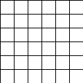
building a grid like this:
The reason interior lines in this grid are the same thickness as the lines around the edge
is because the rectangles overlap with each other.
That is, the upper-left rectangle’s right edge is right on top of the
next rectangle’s left edge.
The special case of adding 0.5 to each coordinate when drawing the square
applies to all outline polygon-based shapes that just pass color,
but does not apply when a pen
is passed as the last argument to create the shape.
For example, if using a pen of thickness 2 to draw a rectangle, we get a
shape that has a border drawing the row of pixels just inside and just outside
the shape. One might imagine that a pen of thickness 1 would draw an outline around the shape with
a 1 pixel thick line, but this would require 1/2 of each pixel to be illuminated, something
that is not possible. Instead, the same pixels are lit up as with the 2 pixel wide pen, but
with only 1/2 of the intensity of the color. So a 1 pixel wide black pen object draws
a 2 pixel wide outline, but in gray.
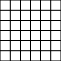
When combining pens and cropping, we can make a rectangle that has a line that is one pixel
wide, but where the line is drawn entirely within the rectangle
and we can use that to build a grid now too, but this grid has doubled lines on the
interior.
While this kind of rectangle is not useful for building grids, it
is important to be able to build rectangles whose drawing does not
exceed its bounding box. Specifically, this kind of drawing is used
by frame and empty-scene so that the extra drawn pixels
are not lost if the image is later clipped to its bounding box.
2.2.12 Exporting Images to Disk
In order to use an image as an input to another program (e.g., Photoshop or
a web browser), it is necessary to represent it in a format that these programs
can understand.
The save-image function provides this functionality,
writing an image to disk using the PNG format. Since this
format represents an image using a set of pixel values, an image written to disk
generally contains less information than the image that was written, and cannot be scaled
or manipulated as cleanly (by any image program).
The save-svg-image function writes an SVG file format
representation of the file to the disk that, unlike save-image produces
an image that can still be scaled arbitrarily look as good as scaling the
image directly via scale.
Writes an image to the path specified by filename, using the
PNG format.
The last two arguments are optional. If present, they determine the width
and height of the save image file. If absent, the width and height of the image is used.
Writes an image to the path specified by filename, using the
SVG format.
The last two arguments are optional. If present, they determine the width
and height of the save image file. If absent, the width and height of the image is used.


